Context
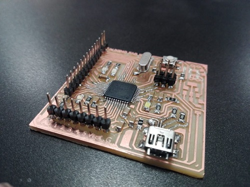
This project focused on building a general-purpose microcontroller board that could be reused across different prototypes and experiments, rather than a single-purpose device. The goal was a practical electronics platform flexible enough for different assignments, USB-driven communication, and future development work.
Choosing the ATmega32U4 was a deliberate decision rather than a default one. Unlike simpler AVR chips that rely on an external USB-to-serial bridge, the 32U4 has native USB support built directly into the silicon, which meant the board could enumerate as a USB device on its own and cut down on the parts count and failure points that come with an extra bridge chip. That single choice shaped nearly every later decision in the project, from the crystal used for clock timing to the way the USB traces were routed and terminated.
02Reusable and manufacturable, at once
A reusable board has to balance flexibility with manufacturability. The challenge was selecting the right microcontroller architecture, ensuring the board could be fabricated reliably, and validating that the design would support real programming workflows through Arduino and Python toolchains.
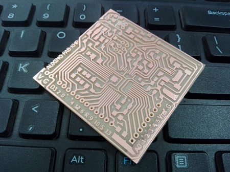
Because the board was meant to be milled rather than professionally fabricated, every design decision had to account for the limitations of in-house PCB milling: trace widths and spacing had to stay well clear of the mill bit's minimum tolerances, and the layout had to avoid tight clearances around the USB connector and crystal that a commercial fab would have handled without complaint. On top of the physical constraints, the design had to leave enough general-purpose I/O broken out to headers that the board would still be useful for projects that hadn't been imagined yet, without turning the layout into a tangle of crossing traces on a two-layer board.
03From schematic to working board
The board was designed after reviewing the ATmega32U4 datasheet and mapping the required power, USB, and I/O needs. Working through the datasheet meant identifying which pins carried alternate functions, confirming the decoupling capacitor placement recommended for the USB regulator, and working out a pinout that kept commonly used peripherals grouped together on the header rows so the board would be easy to breadboard against later.
The next stages included updating the schematic, fixing design issues, milling the PCB, soldering components, and then validating the board by burning the bootloader and uploading simple test programs. Milling surfaced problems that hadn't been visible on screen — a couple of traces routed too close together for the mill bit to cleanly isolate, and a footprint that needed adjusting once the actual component was placed against it. Each was fixed by revisiting the schematic and re-running the milling pass rather than patching the physical board.
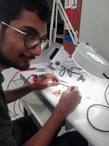
Bringing the board to life for the first time meant confirming power regulation was stable, that the USB connection enumerated correctly on a host machine, and that the bootloader could be burned without errors. This built a much more concrete understanding of how a schematic's abstractions map onto physical copper, solder joints, and firmware behavior.
04System thinking
Hardware
The board integrated a USB-enabled AVR controller, power regulation, I/O access, and support components for a flexible development environment. Support circuitry included the crystal and load capacitors needed for stable USB timing, pull-up resistors on the data lines, and a voltage regulator so the board could be powered either from USB or from an external supply during standalone use.
Software
It was successfully tested in Arduino and Python-based workflows, showing how the same hardware could support different programming environments. On the Arduino side the board could be programmed like any Leonardo-class device once the bootloader was in place, while Python scripts confirmed the USB serial interface behaved predictably for automated testing and data logging.
Results and lessons
The outcome was a board that could serve as a reusable prototyping foundation for future embedded projects — validated through a working bootloader, clean USB enumeration, and tested programming workflows in two different languages. That combination made it a genuine base to build on rather than a one-off proof of concept.
More importantly, the process reinforced how much value lies in understanding the datasheet, the pinout, and the system-level design decisions behind a board that may seem simple but becomes powerful when used correctly — and how much of that value gets lost if the fabrication constraints of in-house milling are treated as an afterthought instead of a first-order design input.