Context
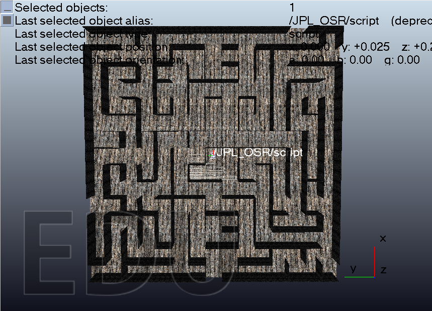
The project set out to answer a deceptively simple question: could a wheeled planetary rover, dropped into the center of an unmapped 15×15 grid maze, drive itself out while building a complete and accurate map of every traversed cell? Rather than simplifying the system into a differential-drive platform, the build used a full simulated model of the JPL Open Source Rover, a six-wheeled, four-steerable-joint rocker-bogie platform that introduced realistic vehicle kinematics, wheel slip, and collision behavior into the navigation problem.
The simulation ran in CoppeliaSim Edu using the Bullet 2.78 physics engine inside a 15m × 15m maze built from 1m × 1m cells with 0.1m walls. The maze contained no unreachable pockets, but there were open exits along its outer boundary that the rover had to learn to identify and treat as forbidden; otherwise, the robot could confuse them with ordinary corridors and leave the maze prematurely.
02Drive like a rover, not a point mass
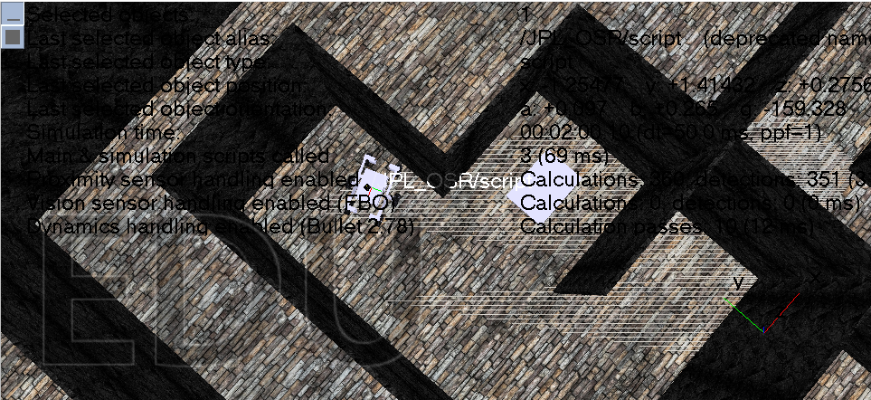
There were two interconnected challenges. First, the rover had to navigate continuously through the maze without leaving it, using realistic vehicle motion rather than pivoting in place. This meant implementing true Ackermann steering geometry, computing different inner and outer wheel angles and speeds for each turn, and converting linear velocity commands into the correct angular velocity of each of the six independently driven wheels.
Second, the system needed to map the maze as it explored it, visiting every reachable cell and recording each cell's grid position, position in meters relative to the maze center, and which sides were open or walled. Repeated readings of the same cell needed to be merged to cancel out sensor noise and produce a reliable map instead of a noisy grid.
03What was built
The rover carried a single Hokuyo URG-04LX-UG01 laser rangefinder on a rotating joint, sweeping a 240° arc to read distance in three directions — left, front, and right — at each decision point. A four-state machine managed the full system behavior: FORWARD cruised at 0.50 m/s, reading the laser every cycle and slowing to 40% speed as a wall approached; BACKUP reversed at 0.25 m/s to safe clearance before a fresh scan; TURN_ACK executed a 90° Ackermann turn using precomputed inner and outer steering angles, tracked through a low-pass-filtered yaw estimate; and SPIN_180 performed an in-place counter-clockwise spin reserved for true dead ends.
At every junction, the rover evaluated left, straight, right, and back in that priority order and selected the direction leading to the least-visited neighboring cell. This made the robot actively steer toward unexplored territory rather than simply following a wall. A tried[] list at each junction prevented repeated failed attempts, and the state reset cleanly once the rover physically advanced into a new cell.
04System thinking
Sensing and fallback
The sensing pipeline used a three-tier fallback approach: reading the laser via string signal, point cloud, or joint rotation plus proximity sensor, whichever the simulation environment supported. This protected the rover from single-API failures and improved robustness under changing runtime conditions.
Kinematics and navigation
True Ackermann steering was computed using physical geometry values including track width, wheelbase, and wheel radius. The turning radius and backup clearance were tuned to allow rotation within a 1m corridor while keeping wheels rolling without excessive slipping.
Cell classification
Laser readings under ~1.10m were treated as walls, readings between ~1.10m and 4.50m were considered open corridor, and readings at or beyond 4.50m were treated as maze exits and explicitly excluded from the map. This prevented the rover from mistaking the boundary for a traversable corridor.
Mapping logic
Every visit to a cell merged newly read openings with prior readings, allowing the system to avoid false walls or false openings from noisy single scans and preserve a stable map.
Results and lessons
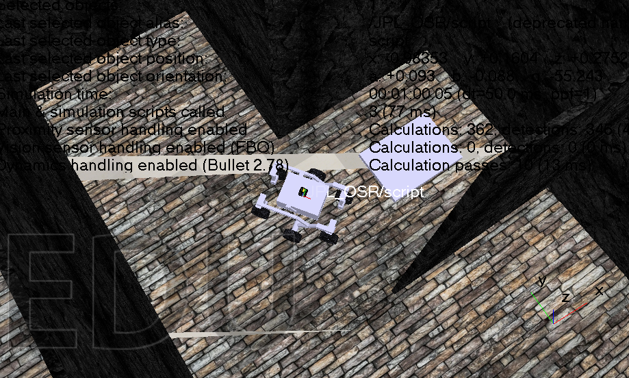
The rover successfully traversed the full maze and produced a complete cell-by-cell map, including a rendered grid view and a diagnostic printout, while never crossing an open boundary exit. The work exposed several realistic simulation issues: a laser API that did not exist in the installed CoppeliaSim version, junction logic that could trap the rover in infinite loops, exit readings being misclassified as open corridor data, and Ackermann turns clipping walls until the turning radius and backup clearance were retuned.
The broader lesson was that autonomous navigation engineering is rarely about a single headline algorithm. A large share of the real effort lives in sensing robustness, state transitions, edge-case handling, and making the system resilient to API quirks, sensor noise, and repeated junction encounters. The project therefore became a strong demonstration of disciplined system design rather than just maze traversal.